Visual Studio 2010 adds a whole new series of modeling tools to the product, including UML modeling. In this post I want to discuss the Layer diagram and its relation to building enterprise applications.
The Layer Diagram
Visual studio 2010 now comes with new modeling tools, which you can reach through the architecture menu from Visual Studio 2010 (I’m using the Ultimate edition):

This will open the Add New Diagram dialog:
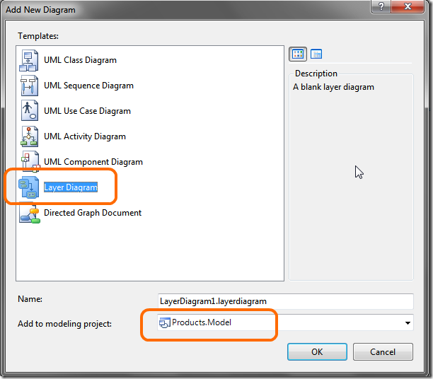
Select Layer Diagram. If you don’t yet have a Modeling Project in your solution, another dialog will open so you can name your new modeling project.
You should now see an empty layer diagram, so let’s add some layers. Open the toolbox:
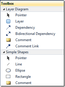
Double click the Layer item in the toolbox (doing this will lock the toolbox into adding layers, if you single click it you will need to go back to the toolbox for each layer) and click the layer diagram three times to add three layers, stacked vertically. Name the top one Presentation, the middle one BLL (Business Logic Layer) and the bottom one DAL (Data Access Layer).
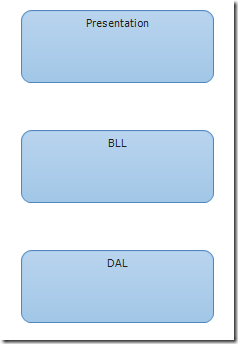
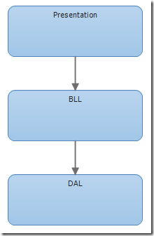
So now we have three layers. Now let’s add a couple of dependencies. I want the presentation layer to use the BLL layer, but not reversed, so let’s model this by adding a dependency  from the Presentation layer to the BLL. Let’s also do the same for the BLL to the DAL:
The Enterprise Application Skeleton
Having a layer diagram is nice, but how can it help you with your development? The layer diagram can help by verifying your solution and projects comply with the layer diagram. As an example I want to use the Enterprise Skeleton solution I use for enterprise development. In its simple version there are 4 projects (excluding the modeling project): one for the presentation layer, one for the BLL and one for the DAL. The fourth project contains the data carrier objects that travel between layers; the DAL is responsible for retrieving and storing these objects, the BLL will check these objects using the business rules and the presentation layer will display these objects.
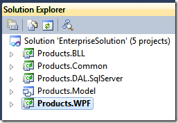
Let’s use this solution with the layer diagram.
Adding layer verification to your solution
Open Visual Studio with this kind of solution and with your layer diagram (part of a modeling project in your solution). Now drag and drop each project to its appropriate layer. Drop the Products.Common onto the DAL layer (this is a mistake which we’ll discover soon with the verification feature). Each time you do this you will see a counter appear on the layer, counting the number of projects mapped to the layer…
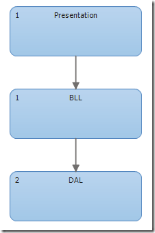
However, you cannot see here which project is mapped to each layer. Back to the architecture menu. Open “Windows –> Layer Explorer”, which displays the mappings:

If you select a specific layer in the layer diagram, this window will show only projects mapped to it. You can do the same by: right-click on a layer, select View Links.
Validation the solution
Right-click the layer diagram and select Validate Architecture:
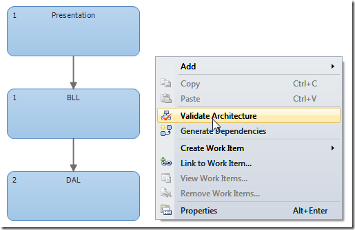
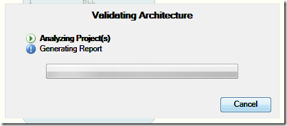
Visual studio will start to analyze your code and may return a bunch of validation errors:

Open the error list window to see these errors:

From here you can do several things: create a work item to correct the error, suppress the error, or investigate the error:
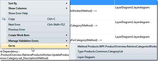
The screenshot illustrates the last action. With this you can go to the method or type involved in the validation error.
The problem we are facing here is actually because I put the Products.Common project into the DAL. But the presentation layer also needs the types in this project, but we’re not allowing referencing the DAL from the presentation layer. We could add this dependency (please don’t), or we can fix the problem.
Fixing the problem
Add another layer to the layer diagram, calling it Common. This layer will contain all types common to the other layers, so add dependencies from these layers to the common layer. Finally drag the Products.Common project to the common layer.
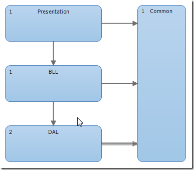
One more thing: we need to remove the Products.Common project from the DAL layer. Select this layer, in the Layer Explorer you should see two projects. Remove the common project. Now verify again. You should have 0 errors.
Automating Validation
This validation is a powerful tool to prevent layering mistakes from creeping into your solution. So can we automatically run this whenever we build?
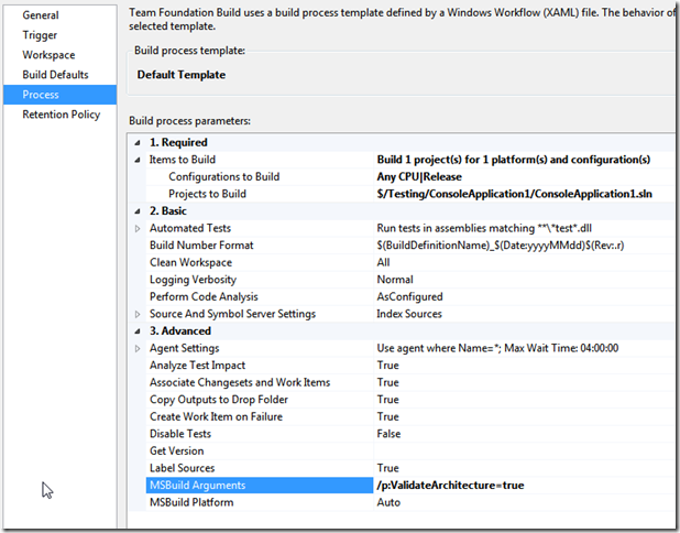
Yes we can! One way is to set the Validate Architecture property of the modeling project to true. Then each time you build the solution the layer diagram will verify. This can take same time for each build, so it is better to do this using Team build. You can enable validation using the /p:ValidateArchitecture=true option. To do this, open your build definition and set the “MSBuild Arguments” property like this:
Generating dependencies from your solution
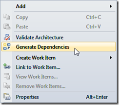
Another thing you can do is to add the layer dependencies from your solution. Right-click the layer diagram after adding your layer (and which you mapped to your projects). Then select the Generate Dependencies menu.
What else is there?
What else can you do with the layer diagram? Look at the previous screen shot. If you’re connected to VSTS you can link and create work items.